


Sintering oven LH 15/12for general purposeslaboratorymulti-gas

Add to favorites
Compare this product
Characteristics
- Function
- sintering
- Applications
- for general purposes, laboratory
- Type
- multi-gas
- Sterilization chamber material
- stainless steel, ceramic fiber
- Temperature control
- with ventilation system
- Configuration
- floor-standing
- Number of doors
- 1-door
- Other characteristics
- automatic, high-performance
- Temperature range
Max.: 1,400 °C
(2,552 °F)Min.: 1,200 °C
(2,192 °F)- Capacity
Max.: 216 l
(57.06 gal)Min.: 15 l
(3.96 gal)
Description
Introduction
LH models: multi-layer insulation with light refractory bricks and special backup insulation. LF models: fiber insulation with corner bricks to reduce heating and cooling times.
Overview
The LH/LF chamber furnace series (examples: LH 15/12 – LF 216/14) is designed for laboratory and industrial thermal processes and is available with either brick-based insulation (LH) or a combined corner-brick + low heat‑storage fiber insulation (LF). Multiple Tmax options and a range of internal volumes allow selection according to process and load requirements. A broad set of optional equipment enables adaptation to specific atmospheres, cooling profiles and extraction interfaces.
Standard equipment
Additional equipment
Technical specifications (excerpt)
Model | Tmax (°C) | Inner W x D x H (mm) | Volume (l) | Outer W x D x H (mm) | Load (kW) | Connection | Weight (kg)
LH 15/12 | 1200 | 250 x 250 x 250 | 15 | 680 x 860 x 1230 | 5 | 3‑phase | 170
LH 30/12 | 1200 | 320 x 320 x 320 | 30 | 710 x 930 x 1290 | 7 | 3‑phase | 200
LH 60/12 | 1200 | 400 x 400 x 400 | 60 | 790 x 1180 x 1370 | 8 | 3‑phase | 300
LH 120/12 | 1200 | 500 x 500 x 500 | 120 | 890 x 1180 x 1470 | 12 | 3‑phase | 410
LH 216/14 | 1400 | 600 x 600 x 600 | 216 | 990 x 1280 x 1590 | 26 | 3‑phase | 470
LF variants correspond to the LH internal dimensions; LF models have reduced heat storage for shorter heating/cooling times.
Notes
External dimensions and connected load can vary with optional equipment. For multi‑range voltage versions the connected load refers to the highest permissible connection voltage. In some configurations heating occurs between two phases only.
Features / Technical data
LH models: multi-layer insulation with light refractory bricks and special backup insulation. LF models: fiber insulation with corner bricks to reduce heating and cooling times.
Overview
The LH/LF chamber furnace series (examples: LH 15/12 – LF 216/14) is designed for laboratory and industrial thermal processes and is available with either brick-based insulation (LH) or a combined corner-brick + low heat‑storage fiber insulation (LF). Multiple Tmax options and a range of internal volumes allow selection according to process and load requirements. A broad set of optional equipment enables adaptation to specific atmospheres, cooling profiles and extraction interfaces.
Standard equipment
- Tmax selectable: 1200 °C, 1300 °C or 1400 °C
- Dual‑shell housing of textured stainless steel with additional fan cooling to keep external surface temperature low
- High furnace chamber with five‑sided heating for improved temperature uniformity
- Heating elements mounted on support tubes to ensure free radiation and extended element life
- Controller hung on the furnace door and removable for convenient operation
- Embedded SiC plate in the floor for bottom‑heating protection and a flat stacking surface
- Brick‑on‑brick door seal, hand fitted
- Generously dimensioned heating power for short ramp‑up times
- Self‑supporting arch for stability and dust protection
- Motorized exhaust flaps and freely adjustable air inlet in the furnace floor
- Base included
- Controller B500 with touch operation (5 programs × 4 segments) and NTLog Basic for process data recording via USB
- Use within the defined limits of the operating instructions
Additional equipment
- Parallel swinging door (reduces operator exposure to heat radiation)
- Lift door with electro‑mechanical linear drive for opening when hot
- Cooling system for controlled cooling by temperature gradient or preset fresh‑air volume (controller‑segment controllable)
- Protective gas connection for purging with non‑flammable process gases (N2, Ar, He, forming gas)
- Manual or automatic gas supply systems
- Stainless steel hood as interface to customer extraction system
- Scale for measuring weight loss during annealing
- Over‑temperature limiter with adjustable cut‑out
- Process control and documentation via VCD software package
Technical specifications (excerpt)
Model | Tmax (°C) | Inner W x D x H (mm) | Volume (l) | Outer W x D x H (mm) | Load (kW) | Connection | Weight (kg)
LH 15/12 | 1200 | 250 x 250 x 250 | 15 | 680 x 860 x 1230 | 5 | 3‑phase | 170
LH 30/12 | 1200 | 320 x 320 x 320 | 30 | 710 x 930 x 1290 | 7 | 3‑phase | 200
LH 60/12 | 1200 | 400 x 400 x 400 | 60 | 790 x 1180 x 1370 | 8 | 3‑phase | 300
LH 120/12 | 1200 | 500 x 500 x 500 | 120 | 890 x 1180 x 1470 | 12 | 3‑phase | 410
LH 216/14 | 1400 | 600 x 600 x 600 | 216 | 990 x 1280 x 1590 | 26 | 3‑phase | 470
LF variants correspond to the LH internal dimensions; LF models have reduced heat storage for shorter heating/cooling times.
Notes
External dimensions and connected load can vary with optional equipment. For multi‑range voltage versions the connected load refers to the highest permissible connection voltage. In some configurations heating occurs between two phases only.
Features / Technical data
- Available Tmax options: 1200 °C, 1300 °C, 1400 °C
- Two insulation concepts: LH = multi‑layer light refractory bricks; LF = fiber insulation with corner bricks
- Five‑sided heating and tubular heating elements for uniform temperature and long life
- Controller B500 (touch) with NTLog USB data recording; VCD package for extended process control and documentation
- Options for controlled cooling, protective gas purging, exhaust hood and weighing systems
- Floor protection via embedded SiC plate; base included; several door options
Catalogs
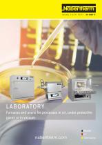
LABORATORY FURNACES
92 Pages
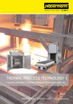
Thermal Process Technology
102 Pages
Other Nabertherm products
Furnaces up to 1400 °C


Related Searches
- Heating furnace
- Laboratory furnace
- Benchtop furnace
- 1-door furnace
- Stainless steel furnace
- Drying furnace
- Automatic furnace
- Dental laboratory furnace
- Floor-standing furnace
- Forced air oven
- High-temperature furnace
- Heat treatment furnace
- General purpose oven
- Muffle furnace
- Compact furnace
- Scientific research furnace
- Annealing furnace
- Thermal furnace
- Zirconia furnace
- High-performance furnace
*Prices are pre-tax. They exclude delivery charges and customs duties and do not include additional charges for installation or activation options. Prices are indicative only and may vary by country, with changes to the cost of raw materials and exchange rates.
About MedicalExpo
MedicalExpo is a marketplace that offers B2B players a complete experience, from product sourcing to purchase. MedicalExpo is an entity of VirtualExpo Group.
Are you a buyer?
Are you a supplier?